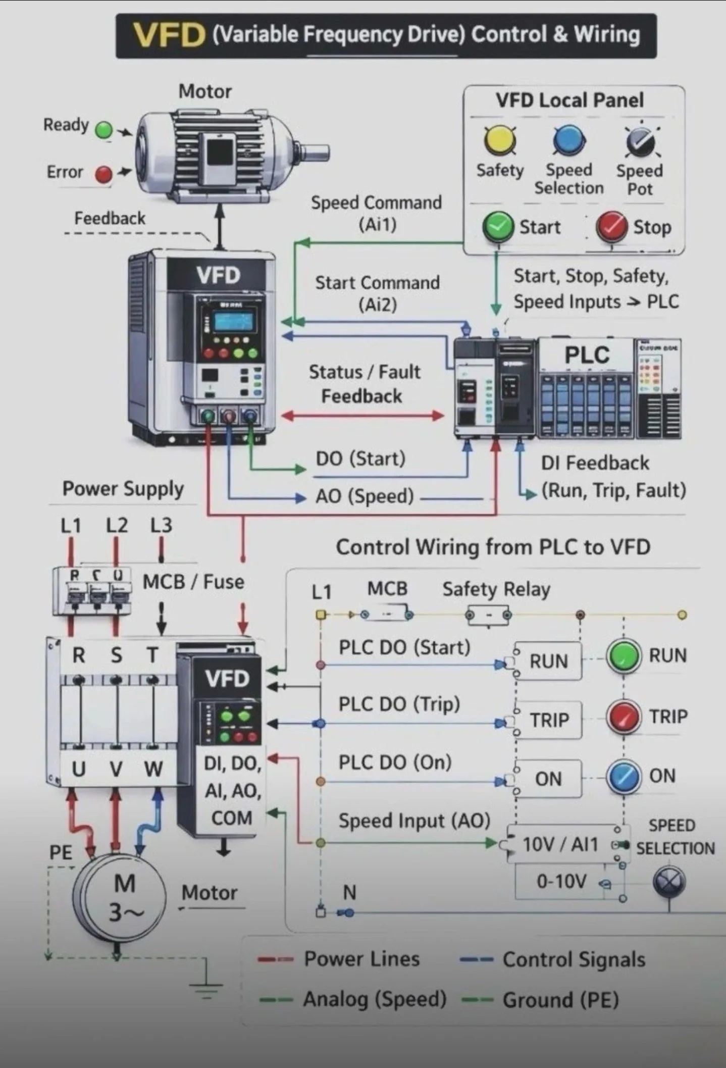
System Components & Flow
The system is divided into two main sections: the physical power/control connections and the logical signal flow.
A. VFD Local Panel: This represents the operator interface. It includes physical buttons for Start/Stop, a Speed Potentiometer for manual speed adjustment, and a Safety status indicator. These inputs are typically fed into the PLC.
B.PLC (The Brain): The PLC receives inputs from the local panel and sends commands to the VFD.
C.Outputs to VFD: Digital Output (DO) for the Start command and Analog Output (AO) for the Speed reference (typically 0-10V or 4-20mA).
D.Inputs from VFD: Digital Inputs (DI) provide feedback on the motor’s status (Run, Trip, or Fault).
E. VFD (The Controller): It acts as the bridge between the control logic and the motor. It takes the low-voltage signals from the PLC and converts the incoming 3-phase power (L1,L2,L3) into a variable frequency output (U,V,W) to control the motor’s speed and torque.
Wiring Breakdown
The lower half of the diagram illustrates the specific electrical connections:
into
1. Power Wiring (Red Lines):
a. Main power enters through an MCB/Fuse
the VFD terminals R, S, T.
b. The VFD outputs power to the Motor via terminals U, V, W.
c. PE represents the protective earth (grounding).
2. Control Wiring (Blue/Green/Dashed Lines):
a. Digital Signals: PLC outputs trigger relays (like the “RUN” or “TRIP” indicators shown) to signal the VFD to start or stop.
b. Analog Signals: The “Speed Input (AO)” sends a variable voltage (0-10V) to the VFD’s Al1 terminal to define how fast the motor should spin.
c. Safety Circuit: Often involves a Safety Relay that can cut power or disable the drive in an emergency.

Responses (0)
Join the Conversation
Only registered members can respond. Log in or create a free account to share your thoughts.